
Appearance
Code Structure
Writen by Chunxiao Xu, PhD
Preset and Scene
The rendering system is composed of two main classes: one belonging to the Preset layer and the other to the Scene layer. A Preset class object (with the 'Preset' suffix) can be initialized from a preset file (XML or JSON). These initialized Preset objects are then used to instantiate the corresponding Scene objects.
Coordinate System
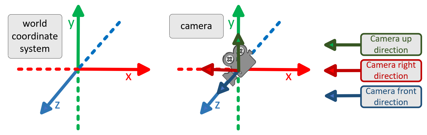
Coordinate System World and Camera Coordinate System
The world coordinate system follows a right-handed convention.
Initially, the coordinate system followed PBRT, and then Mitsuba. For the convenience of 3D reconstruction, we change the coordinate system. Now The camera coordinate system in Crystal is the same as OpenGL.
The point cloud output will still be converted to the Colmap coordinate system.
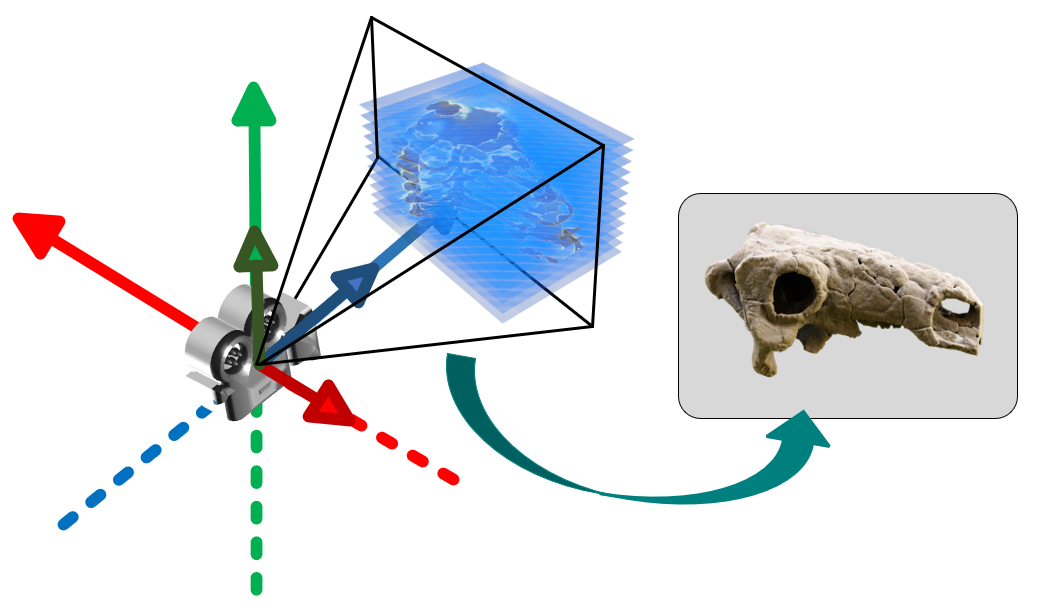
Raster space and Screen space
In the camera coordinate system, the camera is oriented along the negative z-axis, with the up vector aligned with the positive y-axis and the right direction corresponding to the positive x-axis.
- Image Coordinate System: For an image with width w and height h (the resolution of the film), the pixel range in the image is to .
- Raster Coordinate System (for imaging film): The range of the raster coordinate system is to . A pixel in the raster coordinate system corresponds to the range to .
- Screen Coordinate System: The range of the screen coordinate system is to .
In the image space, the vertical coordinate has lower values at the top and higher values at the bottom, which is the opposite of the camera's observation. Similarly, the horizontal coordinate is also reversed. Therefore, the Screen2Raster transformation performs coordinate flipping in both the vertical and horizontal directions.
The screen in Crystal is the normal NDC space and the same as OpenGL. Namely, , and are all in range . For Screen2Raster transformation:
- Horizontal coordinate, Transforms the range to , where maps to , and maps to .
- Vertical coordinate, Transforms the range to , where maps to and maps to .
The near plane in NDC is , and the far plane in NDC is . The range of is also in Raster plane.
Some concept in Crystal
Now, the coordinate system of Crystal is the same as OpenGL.
In glm::perspective function, given the aspect, distance of near and far plane (), the martix is:
[ 2*n/(r-l)   0          (r+l)/(r-l)      0         ]
[ 0           2*n/(t-b)  (t+b)/(t-b)      0         ]
[ 0           0          -(f+n)/(f-n)  -2*f*n/(f-n) ]
[ 0           0          -1               0         ]
where and represent the left and right boundaries of the near plane, respectively. and represent the up and bottom of the near plane, respectively.
When and :
[ n/r   0     0             0           ]
[ 0     n/t   0             0           ]
[ 0     0    -(f+n)/(f-n)  -2*f*n/(f-n) ]
[ 0     0    -1             0           ]
or using the FOV version, set , aspect=w/h (set as ap):
[ 1/(ap*thf)   0       0            0           ]
[ 0          1/thf     0            0           ]
[ 0            0     -(f+n)/(f-n)  -2*f*n/(f-n) ]
[ 0            0      -1            0           ]
The last line has a negative sign, which means in camera coordinate system, is map to . Within the visible range (perspective projection cone), means they still greater than in NDC.
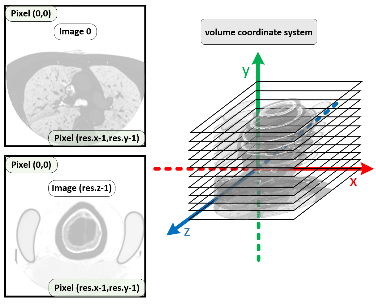
Volume Coordinate System
The resolution of the three axes of the volumetric data is denoted as [res.x, res.y, res.z], while the voxel dimensions along these axes in world space are represented as [vs.x, vs.y, vs.z]. The resolution and voxel dimensions are multiplied element-wise to obtain the actual size of the volumetric data, denoted as [v.x, v.y, v.z]. In the local coordinate system of the volumetric space, the coordinate range of the volumetric data is from [0, 0, 0] to [v.x, v.y, v.z].
The origin of the visualization space is at the center of the volumetric data. The light sources are defined within the visualization space, including point lights, area lights, directional lights and panoramic HDR environment lights. All of these light sources are directed towards the origin of the visualization space and are used to illuminate the medical image volume data.
The transformation of the volume data from volume space to world space consists of the following steps: (1) translation by [-v.x/2, -v.y/2, -v.z/2]; (2) rotation (to ensure the center of rotation is at the center of the volume's bounding box); and (3) another translation.
Steps (1) and (2) are collectively referred to as the VolumeToVisSpace transformation, while the combined operations of (1), (2) and (3) are referred to as the VolumeToWorld transformation. In general, step (3) is not applied, allowing the light sources to always point towards the center of the volume data.
Light Coordinate System
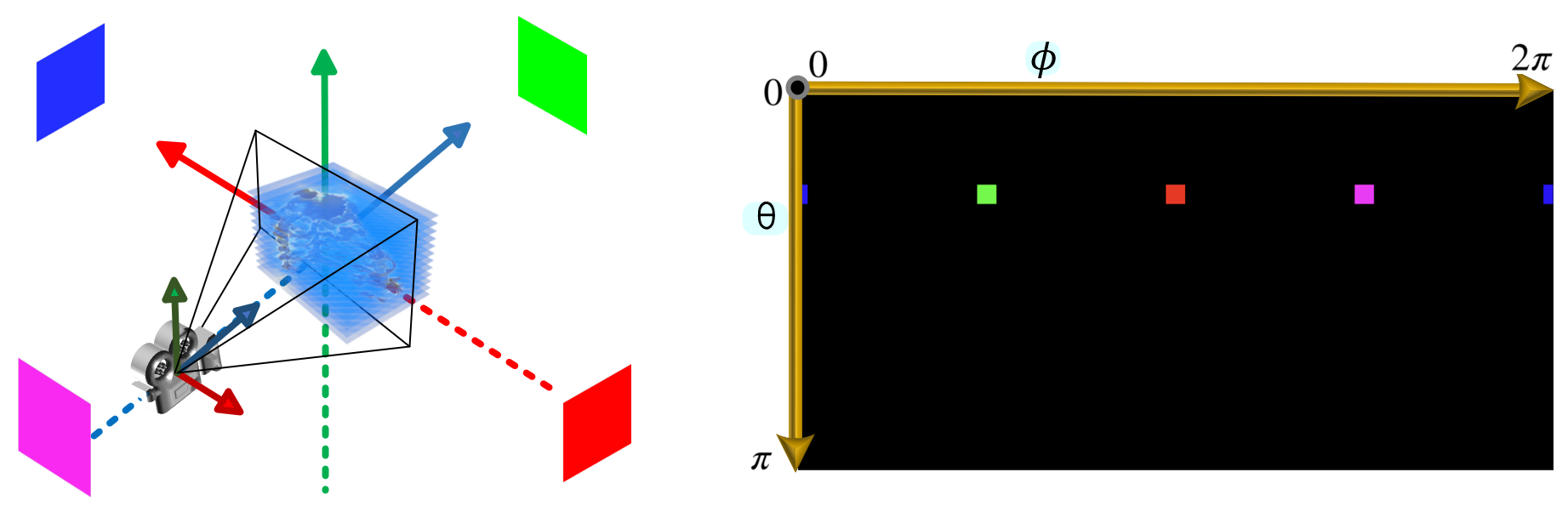
All fundamental light sources (point lights, area lights and directional lights) are defined using spherical coordinates (latitude and longitude), with the direction always pointing towards the origin of the visualization space, which corresponds to the center of the volume data.
The representation of HDR panoramic environment light in the [panoramic coordinate system]:
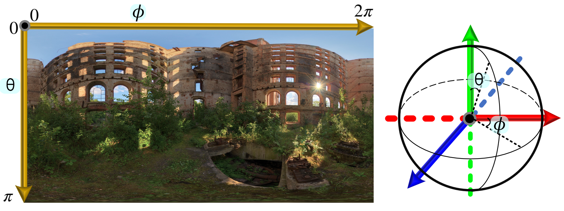
The following figure illustrates the initial state of the HDR panoramic environment light in the visualization space:
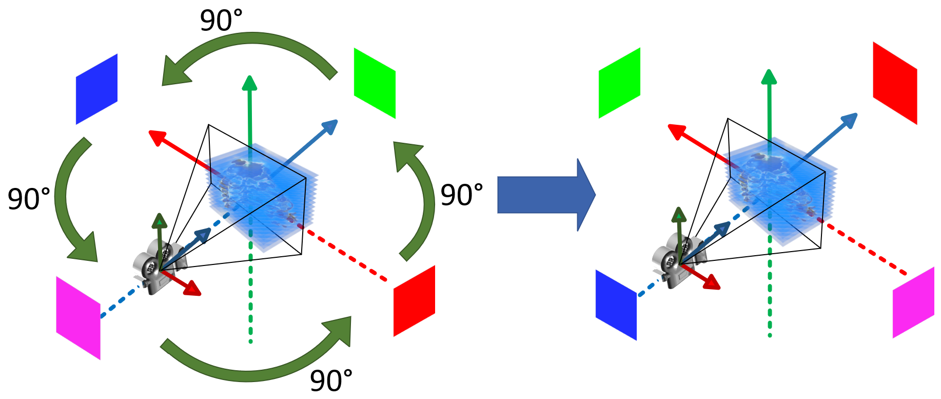
In the visualization space, the panoramic environment light is typically rotated around the y-axis. The following figure shows the result after a 90-degree rotation:
Mitsuba .vs. Crystal
The camera coordinate system in Mitsuba differs from that used in Crystal. Specifically, they are both the right-handed, but the orientations of the x-axis and z-axis in Mitsuba are reversed compared to Crystal.
PBRT .vs. Crystal
In PBRT, the camera follows left-handed coordinate system. The screen space in PBRT keeps aspect of the output image. Namely, if w > h, the width range of screen space in PBRT is , the height range remain ; if h > w, the width range is , while the height range becomes .
Volume
Conventional Volume Data
The rotate way of the volume is as follows: first, rotate along axis, and then rotate along axis.
Volume Flip and Permute
The volumetric data may undergo flipping along the , , and axes, respectively.
Additionally, it may be permuted across the -, -, or - planes, which is analogous to a specific form of rotation. For example, a volume with the original resolution [A, B, C], when permuted along the - plane, will have its resolution transformed to [B, A, C].
Volume-Loader
In Crystal, each scene preset file includes a default volume file. Users can also drag new volume files or load data from buffers. The processing logic is as follows:
- If the newly loaded volume contains only Mask1, the resolution of Mask1 must match that of the original Intensity.
- If the newly loaded volume contains both Intensity and Mask1, their resolutions must be identical.
- If the newly loaded volume contains only Intensity and its resolution differs from that of the original volume, the memory resources will be reallocated. If the resolution remains unchanged, the existing memory resources will be reused.
The default scene preset is used to initialize the [VolumeFile-Class] in the [MedicalVolumeDataPreset-Class]. And the check function [isValid-Func] in [MedicalVolumeDataPreset-Class] will initialize the [VolumeInfoPreset-Class] object using the [VolumeFile-Class] object. The volume data is initialized using [VolumeInfoPreset-Class].
When we load new volume file during rendering, the [.info] or [.dcm] will be used to update the [VolumeFile-Class] object. Then the [VolumeFile-Class] object is used to update the [VolumeInfoPreset-Class] object.
But the original volume may be fliped or permuted. The resolution of new volume must be compared after applying the same flip/permutation as the original volume.
In the [MedicalVolumeDataPreset-Class] (Preset), two sets of variables are maintained:
- resolution_load and voxelSpacing_load: store the original values before any permutation.
- resolution_current and voxelSpacing_current: store the permuted values after transformation.
In the [VolumeInfo-Class] (Scene), only the permuted state is retained:
- resolution: the permuted resolution.
- voxelSpacing: the permuted voxel spacing.
When a new volume is loaded, its resolution is first permuted. This permuted value is then compared directly with the resolution_current (the old permuted value) to determine subsequent processing steps.